
In view of customers' demand for a larger-capacity and more comprehensive security system, as well as other needs, Reolink released a new 36-channel NVR—RLN36.
This article will introduce the details about this NVR model.
1. Features
- It supports all Reolink IP cameras (12MP, 8MP, 5MP, and 4MP). You can connect up to 36 cameras to this NVR.
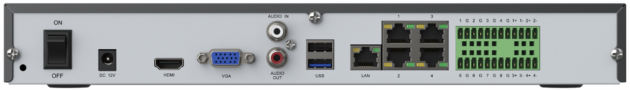
- It has 4 downstream ports (RJ45 ports) and 1 upstream port (LAN port). The maximum speed of the downstream and upstream ports can reach gigabit.
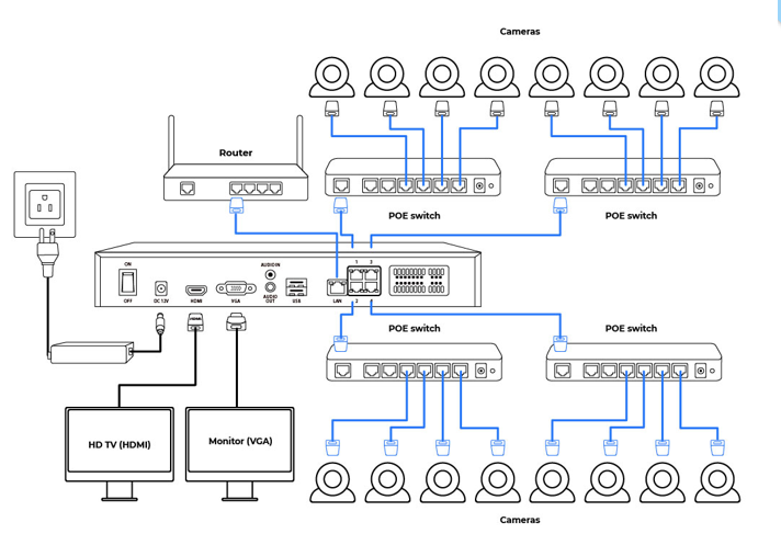
- It does not support PoE. So, if you want to add more than 4 cameras to the NVR, it is recommended to add a PoE switch to the NVR and directly plug the cameras into the switch.
- It supports 3 hard drives and 48 TB capacity in total.
- The device is intended more to be applied in engineering scenarios, and it supports alarm in/out.
- There are 3 USB ports, while others NVR models only has 2.
2. Appearance

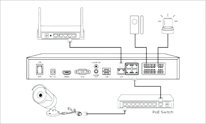
3. Connection Diagram
4. Alarm In/Out
RLN36 can connect 8 alarm input devices and 4 alarm output devices at the same time.
Alarm in: IPC's smart PIR/motion/person/vehicle/pet detection that delivers alarm signals to the NVR;
Alarm out: email/FTP/horn/light and other forms of alarm software or hardware that deliver alarm signals to the user in a more intuitive way.
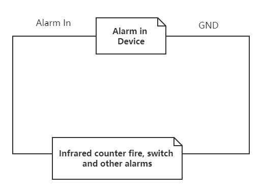
Common alarm-in devices: infrared detector (infrared contrast), electronic fence, door sensor, smoke detector, etc.
The alarm input is to receive the on/off signal, so the positive and negative poles are not distinguished, and the alarm input and GND (ground/earth) can be directly connected to the wires of the alarm-in device. Whether the alarm input device needs a power supply depends on the alarm input device itself.
Common alarm-out devices: siren (horn), buzzer, alarm light, etc.
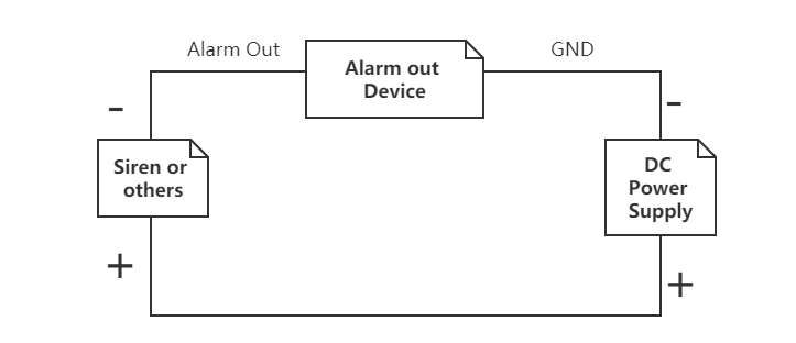
1) DC-powered alarm output device:
a. The alarm out of the VCR is connected to the negative pole of the horn or siren;
b. The positive pole of the horn or siren is connected to the positive pole of the power supply;
c. The negative pole of the power supply is connected to the GND interface of the device;
Note: If it is a DC-powered alarm output, the power supply should be within the range of 12V 1A.
2) AC-powered alarm output device:
It is necessary to disconnect the short-circuit connectors on the main board (JPA1, JPA2, JPA3, and JPA4 respectively) and connect the external relays.